The explanation for each field in this menu is as follows:
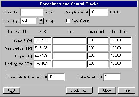
- Block No. (BN)
The control block number. Range: 2-256 (1 is reserved). Control Pack uses the following Blocks depending on its size:
5 Loop Version of Control Pack: 11-15
20 Loop Version of Control Pack: 11-30
50 Loop Version of Control Pack: 11-60
- Sample Interval (T)
The sample interval is in seconds. Range: 1-3600. Default: 5 . For feedback controllers, namely ANN and PIDs, the rule of thumb to set this up is: T = Tc/20, where Tc is the equivalent or dominant time constant of the process. Since these control algorithms are in digital version, you need to set the T properly.
- Control ID Number (CID)
The control algorithm type. Range: 1-16, Default: 1.
CID Block Type Description 1 ANN 1-For-3 ANN 2 PID Standard PID 3 PID-ES PID Error-Squared 4 PID-IT PID Integral-Tracking 5 RAMP Ramping 6 INT Integrator 7 LDLG Lead-Lag 8 SECD Second-Order Filter 9 DTIM Dead-time 10 LIN Linear Function 11 RATIO Ratio 12 HS High Select 13 LS Low Select 14 MS Middle Select 15 LIM Limit 16 LOAD Loader - Controller Type (CT)
The corresponding text related to CID. It is not a field.
- Control Block Status (CS)
The switch to run the block or not. Range: On/Off. It is the same as the CSS field in the ONSPEC PID record. You can change the block status from ONPanel by adding a switch instrument and connect it to the corresponding CS variable. Example: BLK[11].CS. In ONSPEC, you can change it as you usually do by using the CHACSS command.
- Faceplate Number (FN)
The type of faceplate to be used in ONSPEC. Range: 100-110. Default: 100.
- Secondary Block No (SBN)
This field is used only in a cascade loop for feedback controllers (i.e., the ANN and PIDs, CID:1-4).
Let the primary controller be C1 and the secondary controller be C2. You need to set the SBN properly with the following rules:
0 - default, if not a cascade loop or not applicable.
1 - if it is a C1.
N - if it is a C2, let SBN = the block number of C1, where- N is limited to 11-15 for the 5 loop version of Control Pack.
- N is limited to 11-30 for the 20 loop version of Control Pack.
- N is limited to 11-60 for the 50 loop version of Control Pack.
When the proper SBNs are assigned for both C1 and C2, a cascade loop is formed.
- Setpoint (SP)
See Item 11 below.
- Measured Variable (MV)
See Item 11 below.
- Output Tracking Variable (OTV)
The variables 8) to 11) have four fields each. They are EUR index, Tag, Lower Limit Value, and Upper Limit Value.
EUR is the data table name for the 8 byte real number in ONSPEC real-time database. The index range for the popular sizes of ONSPEC is as follows:
- ONSPEC Micro: 100
- ONSPEC Mini: 256
- ONSPEC Basic: 1024
- ONSPEC Power: 4096
To make the configuration simpler, it is designed to have the following mapping between the control block variables and the EURs as defaults. A PIDS.IBM file included in the distribution disk has a 10 block database with the following configuration:
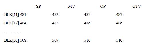
If you have a smaller size of ONSPEC such as ONSPEC Micro and Mini, you will not be able to use the PIDS.IBM file included. You may create a new file with the following mapping between the control block variables and the EURs.
Tag is the ONSPEC Tag that is connected to this EUR variable. You configure the variable based on either EUR or the Tag. You do not need to configure both fields.
Lower Limit Value (LLV) and Upper Limit Value (ULV) are the limits for these variables. Notice that the limits for setpoint and measured variable are in engineering units. Range: All real numbers, but ULV > LLV.
The limits for output and output tracking variable are always 0 to 100 percent for all the feedback controllers, ANN and PIDs. For other control algorithms, the limits for output and output tracking variable can have values in engineering units.
Press or click these buttons to do the following:
- Change to save the configuration.
- Prev to scroll 1 block back.
- Next to scroll 1 block forward.
- Block Info to go to the Control Algorithm Menu.
- Close to leave this Menu.
- Help to bring up the Help Menu.
- Status Word (SW)
The EUI index for the block status word. EUI is the data table name for the 2 byte integer in ONSPEC real-time database. The index range for the popular sizes of ONSPEC is as follows:
- ONSPEC Micro: 100
- ONSPEC Mini: 256
- ONSPEC Basic: 1024
- ONSPEC Power: 4096
The default value: Block No + 60. For example: Block No: 11, Status Word: EUI[71]. Block No: 12, Status Word: EUI[72].
Notice that the Control Pack comes with a pre-configured PID record file, a 20 loop PIDS.IBM file. It will work with all different sizes of ONSPECs. However, for the 50 loop Control Pack, you need to configure the Status Word carefully since the EUI may be used as a Process Model Number.
- Process Model Number (PMN)
The EUI index for the process model number. Range: same as above. the default value: the EUR index value of the Setpoint. For example: Block No: 11, Setpoint: EUR[11], Measured Variable: EUR[12], Output: EUR[13], Process Model Number: EUI[11].
Notice that there are seven built-in process models in the 1-For-3 Control Pack product for computer simulation.
Specify 0 if you want to do the real control of a process.
If you want to do online simulation with the built in process models, specify a model number (1-7) to select the model. See the topic of Process Models for details.